
Have you ever had to discard an entire batch of ash samples for analysis simply because the results between the crucibles differed by a few percent? In microbiological analysis or quality control, temperature inconsistencies in the furnace chamber of a laboratory autoclave are a “silent killer” that distorts our experimental results. Notably, these stringent requirements are similar to maintaining temperature stability in sterilization systems. For example, a temperature fluctuation of just 0.3°C in an autoclave can significantly affect results that meet ISO 17025 standards. This article will uncover the core causes of furnace chamber temperature deviations. From there, we will explore the standard operating solution from Nabertherm (Germany) to ensure 100% uniform crucible cooking.
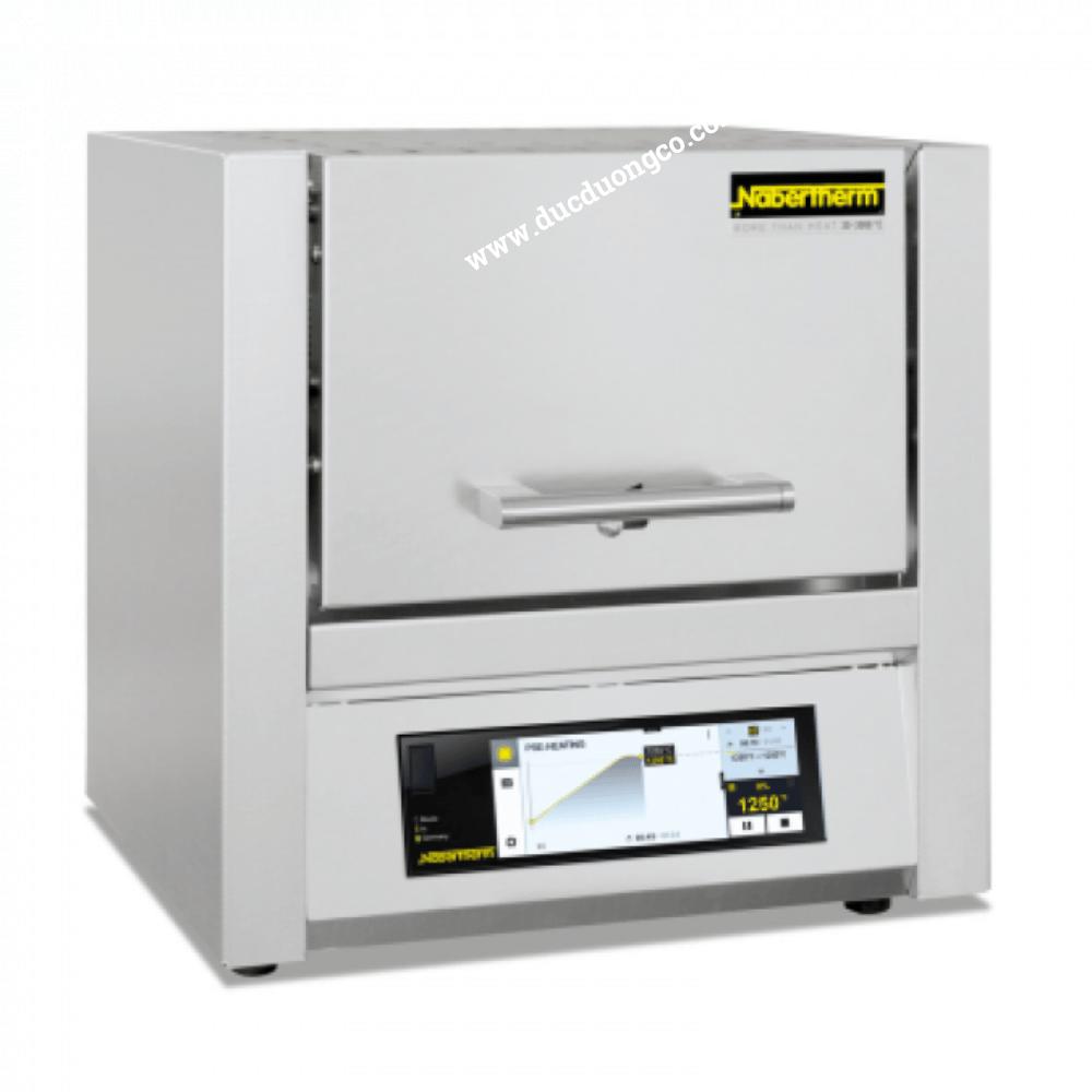
1. Physical Causes of Temperature Deviation in the Furnace
1.1 Temperature Dead Zones in the Furnace
The heat distribution mechanism in a laboratory furnace largely depends on two physical factors: direct thermal radiation from the ceramic heating elements and the natural convection current of air moving within the furnace. However, this energy flow is never absolutely uniformly distributed at every location.
The area near the furnace door always suffers the most significant heat loss due to reverse radiation to the protective casing. Conversely, the corners of the furnace bottom are prone to forming areas with lower-than-average temperatures. It is important to note that localized overheating will occur if the ceramic plates are placed too close to the side walls, where the electric resistance ceramic heating elements are directly integrated and bear the load.
1.2 Negative Impact of Accumulated Exhaust Gases
The process of incinerating organic compounds into ash often generates a large amount of biological exhaust gases such as smoke and steam. If the exhaust system is inefficient, these impurities will quickly accumulate inside the furnace. They inadvertently form a layer of cold air surrounding the material being heated.
The trapped air at the corners of the furnace directly prevents the circulation of natural air convection currents. The direct consequence is a significant drop in temperature at these points compared to the center. This asymmetrical temperature range prevents samples heated at the corners from being heated evenly.
2. DIN 17052-1 Standard on Temperature Uniformity
2.1 Definition of Temperature Error According to the German Standard
To assess whether a laboratory furnace system meets quality standards, international organizations use very strict legal frameworks. The German DIN 17052-1 standard is considered the most reputable measure currently available for quantifying temperature uniformity in the furnace chamber. This standard classifies equipment based on the actual error at fixed measurement points.
According to the technical documentation from Nabertherm (Germany), a standard laboratory device must achieve a maximum geometric error of ±5K (equivalent to ±5°C) in the open workspace. This measurement is performed by distributing a minimum of 9 specialized temperature probes at the corners and center of the furnace chamber.
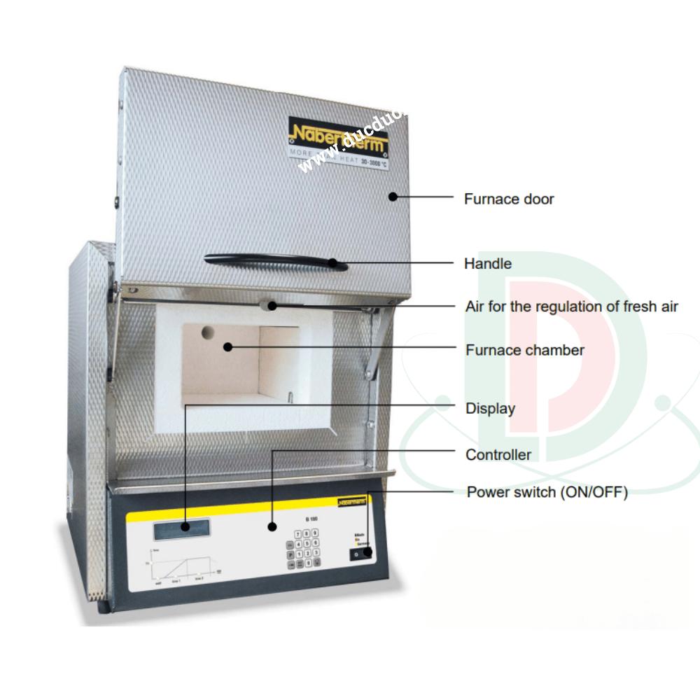
Laboratory furnaces must comply with the German DIN 17052-1 standard
2.2 Differences Between Empty and Loaded Furnaces
We need to understand that the temperature uniformity in an empty furnace never matches that in a loaded furnace. When you fill the chamber with ceramic plates or crucibles, their materials absorb a large amount of thermal energy. This process completely disrupts the manufacturer’s original heat flow distribution chart.
Therefore, accurately reading and understanding the temperature calibration certificate from organizations like Quatest is mandatory. This document helps technicians determine the actual temperature range when operating a loaded furnace. Below is a table of allowable heat deviation parameters for each application segment:
| Target heating temperature (°C) | Standard void space tolerance DIN 17052-1 PDF | Recommended tolerance under actual sample loading |
| 500°C | +-3K | 5°C |
| 800°C | +-5K | 7°C |
| 1100°C | +-5K | 10°C |
3. Sample Arrangement Techniques and Convection Airflow Management
3.1 The Golden Distance Rule Between Crucibles
The arrangement of crucibles in the chamber directly affects the sample’s ability to absorb thermal energy. Technicians must absolutely avoid placing crucibles too close together or stacking them haphazardly. This will create a phenomenon of heat radiation shadowing between the analytical materials.
We need to strictly adhere to the “golden” distance rule by maintaining a minimum gap of 20mm between crucibles. At the same time, you must place samples at least 30mm away from the furnace walls and door. If you need to process a large volume of samples, you should invest in a multi-tiered charging rack system with specialized air vents to optimize space.
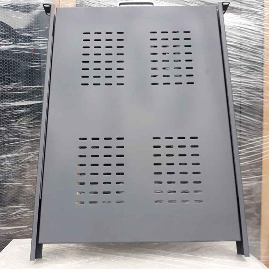
It is advisable to invest in multi-tiered trays for laboratory furnaces
3.2 Operating the Inlet and Exhaust Valve System
The adjustable air inlet system integrated at the front of the laboratory furnace acts as a heat flow regulator. During the initial stage of the organic ash incineration process, the valve should be opened to provide sufficient oxygen for complete combustion. This helps to quickly remove volatile compounds from the chamber.
However, during the holding time, technicians need to partially close the air inlet valve to prevent localized heat loss. Simultaneously, the rear chimney or auxiliary exhaust fan must be kept open. This combination helps stabilize pressure and evenly distribute the heat flow within the furnace.
For guidance on self-checking and quickly troubleshooting 5 temperature distribution errors before the ISO 17025 audit, engineers can submit a detailed request or contact Duc Duong for direct technical support. 4. Setting up the heating program on the intelligent controller
4.1 Managing heat segments to avoid overshoot
Setting up an uncontrolled free heating cycle is a common cause of localized burning on the sample surface. When we force the heating device to heat up too quickly, the current surge creates a very large thermal inertia. This causes the actual temperature of the chamber to exceed the set level (Overshoot), deforming sensitive ceramic structures.
The optimal solution is to divide the heating process into many small segments on the controller. Set up controlled heating ramps with moderate speeds, ranging from 5 K/min to 10 K/min. Accompany this with heating dips at critical temperature points to ensure the thermal energy penetrates evenly to the core of the sample.
4.2 Activating Safety Protection Features and Data Extraction
To prevent the risk of sample destruction in case of technical malfunctions, the use of dual-layer protection features is extremely important. We should choose models with integrated over-temperature limiters that meet Thermal Protection Class 2 standards. This automatic system will immediately cut off all power supply to the heating element when the furnace chamber exceeds the safe limit.
In addition, new generation controllers such as the Nabertherm B510 or C550 controller support a dedicated USB NTLog port. This feature allows you to accurately record the entire actual temperature graph in real time. Through VCD Software, we can easily review and immediately detect abnormal temperature variations.
5. Choosing the Appropriate Mechanical Structure of the Furnace
5.1 Two-Sided Horizontal-Opening Furnaces vs. Vertical Lift-Door Furnaces
The mechanical structure of the furnace shell and door directly affects the system’s ability to maintain thermal stability. When purchasing equipment, laboratories often consider the difference between horizontal-opening doors (Flap door – L series) and vertical-lift sliding doors (Lift door – LT series). The LT lift-door design is superior because it allows the high-temperature side of the furnace to face away from the operator. This protects the technician and minimizes the amount of cold air entering the furnace chamber during the quick opening of the door.
In addition, the two-sided heating mechanism using electric resistance heating elements cast in ceramic insulation ensures perfectly symmetrical energy distribution. To understand the importance of surveying and mapping the heat distribution in laboratory heating equipment, technicians can refer to the temperature mapping guide for autoclaves to apply the same principle to their high-temperature furnace systems.
5.2 Double-Shell Technology Reduces Heat Loss
The furnace shell manufacturing technology is also a core criterion determining the temperature uniformity of laboratory furnaces. High-end models often use a dual-shell stainless steel construction combined with a forced-cooling fan system. This aerodynamic shell prevents heat loss through the furnace walls to the outside environment of the lab. The combination of vacuum-formed ceramic insulation and a double shell helps maintain the ideal temperature in the heating zone.
We can refer to the detailed comparison table of hardware structure affecting heat quality below:
| Mechanical Structure Criteria | Standard-Class Furnace Series | Nabertherm (Germany) Premium Furnace Series |
| Insulation Chamber Lining Material | Conventional refractory brick, prone to cracking | High-grade vacuum-formed ceramic fiber |
| Protective Casing Structure | Single-shell galvanized sheet metal, hot-rolled | Double-shell stainless steel with circulating cooling fan |
| Space Uniformity | Large tolerance, usually deviation of +-15°C or more | Meets the strict DIN 17052-1 standard of +-5K |
6. Periodic Maintenance and Calibration Procedure for Thermocouple Probes
6.1 Thermocouple Degradation
All thermal energy measuring components inside the furnace have a limited physical lifespan over time. Thermocouple probes (commonly Type N made from Nicrosil-Nisil alloy or Type S made from Platinum-Rhodium) often experience surface aging after hundreds of heating cycles at high temperatures above 1000°C. This metal oxidation alters the output voltage of the temperature sensor.
As a result, the controller displays a stable furnace chamber temperature of 1000°C. However, in reality, the temperature at the center of the chamber has surged to 1030°C or dropped significantly. This discrepancy in displayed information completely destroys all efforts to establish a uniform heat distribution program, leading to mass failure of ash analysis samples.
6.2 Frequency of Maintenance for ISO 17025 Standardized Laboratory
To maintain the accurate analytical capabilities of the laboratory autoclave system, a rigorous periodic review schedule is necessary. The use of specialized calibration boxes for independent comparison measurements should be performed every six months. This process helps technicians detect system errors early and promptly reset the temperature offset on the control panel.
For laboratories operating according to the international standard ISO/IEC 17025, linking and synchronizing dynamic measurement procedures is mandatory. Besides checking the autoclave, your laboratory needs to perform all IQ, OQ, and PQ validation steps for the laboratory autoclave. This pressure equipment validation mindset will provide a standardized foundation for the synchronized standardization of the high-temperature autoclave system.
Conclusion
Controlling uneven sample heating requires a holistic approach, from operational procedures to the selection of equipment hardware. Optimizing the spacing of ceramic plates or setting up intelligent heat gradient segments will not yield maximum efficiency if your furnace chamber itself does not meet DIN 17052-1 standards. Don’t let valuable batches of biological or pharmaceutical samples be repeatedly wasted due to localized heat loss in outdated furnaces.
If your laboratory is looking for a heating solution that achieves absolute temperature uniformity and a durable double-walled stainless steel construction, the German-standard Nabertherm product line is the perfect answer. Duc Duong Science and Technology Company is proud to be a trusted partner, specializing in providing high-end analytical equipment solutions and calibration services for large laboratories in Vietnam.
Contact our solution engineering team now to receive a detailed cost estimate and advice on the most optimal furnace configuration for your application:
DUC DUONG SCIENCE AND TECHNOLOGY COMPANY
Address: 1014/67 Tan Ky Tan Quy, Binh Hung Hoa Ward, Binh Tan District, Ho Chi Minh City
Tel: (028) 3762 8042 – 3762 8043 – 3750 8514 – 3750 8793
Fax: 028 37628043
Email: ducduong@ducduongco.com
Website: ducduongco.com
ZALO OA: DUC DUONG SCI
FAQ (Frequently Asked Questions)
Question 1: How to treat blackening of the furnace interior after heating organic samples without affecting the temperature?
Answer: The blackening phenomenon is due to carbon deposits that have not been completely decomposed during the ashing process. We need to address this by running a drum firing cycle (clean burning) at 700°C for 2 consecutive hours. Note that the air intake valve and the rear exhaust pipe must be fully opened to release all the soot adhering to the surface of the ceramic fiber insulation plates, restoring the original heat radiation capacity of the furnace.
Question 2: Can I place the firing tray directly on the bottom surface of the furnace chamber?
Answer: Technicians should absolutely not place ceramic plates or crucibles directly on the ceramic insulation layer at the bottom of the furnace. The bottom of the furnace is the area subjected to the most mechanical stress and has the poorest thermal stability due to upward convection. We should use a specialized Silicon Carbide (SiC) ceramic bottom liner from the manufacturer. This liner protects the ceramic fiber bottom layer from cracking and also acts as a heat accumulator, helping to distribute heat evenly across the bottom of the sample tray.
Question 3: How do I know if my thermocouple probe is showing an inaccurate temperature reading?
Answer: We can perform a verification test using an independent probe system that has been calibrated and certified by Quatest. Place the standard probe in the center of the empty furnace chamber and set the furnace to operate stably at 800°C. After the furnace maintains a stable temperature for 30 minutes, if the readings on the furnace control panel and the standard measuring device differ by more than ±5°C, the thermocouple has aged. At this point, you need to contact a technical unit immediately to replace the probe or reprogram the temperature compensation coefficient (Offset).